 So I have a number of ebay radio triggers for triggering off camera flashes. After modifying the transmitter to get reliable operation I have been quite happy with them. The problem I have with the receivers is that I keep forgetting to turn the power off on them when I done with them.
I also have a Canon A570 IS point and shoot camera and I would like to be able to use off camera flash with it. It has no hot shoe and no other flash trigger output. So I figure I could use some optical triggers for my flash use. I can set the P&S camera for minimal flash output (not that it has a very powerful flash) and optically trigger some remote flash units. Or I can still use an radio transmitter on the camera to cause a a remote flash to fire and that flash can trigger the optical triggers firing additional flash units.
So do I head out and buy a bunch of optical slaves? No way, not me. Instead I make my own. So I take a look on the Internet to see what others have done. Very little out there and I was not happy with the little I found. The better design required a battery to operate the circuit. But I didn't want to have to bother with batteries and power switches that I forget to turn off. So I come up with the following (for those with an electronic background and just wanna know).
 Small and simple. Would only be triggered by a flash. Worked reasonably well if pointed at a firing flash or pointed at an illuminated surface (by the initial flash). Well it almost worked good enough. My little point and shoot would not cause it to trigger a remote flash. Odd.
So I take some flashes to work and look at it with an oscilloscope. Worked great when I used a more powerful flash but with the P&S the sensitivity was there but the pulse time on the output of the slave was not long enough to trigger the connected flash. The above circuit only triggers on the initial edge of the flash pulse. With a more powerful flash the light level increases more slowly before it hits peak output. The P&S camera take very little time to get to its peak. The short time was not long enough to trigger a flash.
So I then came up with the following circuit. It is also self powered (actually uses the trigger voltage from the flash). It is designed for modern low trigger voltage flashes. (All my high trigger voltage flashes I modified so the trigger voltages are only 6 volts or less.) It works fine with my Canon flashes that only have a 4 volt trigger voltage.

The right half of the circuit (Q3 and all above and to the right of it) makes sure that if it only sees a very brief flash pulse it will extend the trigger on time to make sure flash units that want a longer trigger pulse will fire.
A little more complicated but also has a couple of refinements. It has what some manufactures call an ambient light filter. Well my previous one had that as well but this one has a larger operational range.
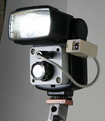
So I came up with a decent working circuit but I needed to house it somehow. I still wanted it to be smallish. I also wanted to put a cable on it so I could plug it into a number of different flashes and be able to aim it at the flash light source and more importantly away from any direct bright lights. I found a bunch of RJ45 cable joiners (I think it is RJ45). Sure its full of stuff but I can take care of that.
Poped it open and figured out how to take out the guts. There still was too much plastic inside the housing that was used to hold things in place. No problem, at least not for someone with a milling machine. So a little while later and I can fit the electronic assembly into the housing.
I wanted a lens for the front of the slave so I grabbed a bunch of lens assemblies I had kicking around. These were the view finder lenses from one time use disposable cameras. Of course they were not the correct size for my application but not a problem, at least not for someone with a milling machine. So I get it all to fit and wired up. Then I decided I would also like to have a jack so I can connect either an additional flash to the unit, or with a cord a flash further away from the optical trigger, or to have the optical trigger and a radio trigger wired together so that both can trigger a flash. So I added a socket/jack on the back of the unit.

It was simple enough and easy to just keep adding the parts wiring them point to point. No circuit board to make. No added wires, just the component leads. None of the parts values are critical. As long as they are in the ball park.
How it works
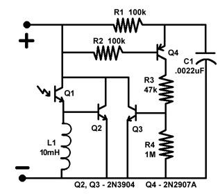
No the inductor does not hold the circuit on longer. Q3 and all the stuff above and to the right hold it on longer. The photo transistor conducts depending on the amount of light. If the light does not change fast then the inductor just looks like a low value resistor. Only if there is a rapid increase in light will a significant voltage drop occur across the inductor. Once you have more than .6 volts on Q2 transistor's base the collector will be pulled to the negative side of the circuit. Now once the collector gets pulled low this will cause the base of Q4 to go low and turn on. Because of this Q4 will feed the charge sitting on C1 to dump through Q4 through R3 and keep Q3 on until the charge on C1 drops. Simple. :)

This shows the flash light put out by my Canon A570 IS. The sharp risetime of the leading edge is so short that the first circuit I used created only a short pulse that would not trigger a flash. Because the first circuit only reacts to, and outputs a pulse, dependent on the length of the rising edge I had to come up with the second circuit.

This is the voltage at the base of Q2 as a result of the light pulse in the above image. The coil responds to the edge but that is enough to get the circuit in action.

This is the same thing but with the horizontal scan set to 10uS per division so the width of the signal can be seen.

This shows the collector of Q4. The transistor was turned on by the trigger + going low. This dumps the charge on C1 through R3 and into the base of Q3 turning it on. Q3 then holds the trigger output low continuing to keep Q4 on until C1 dumps all its charge and there is not enough to keep Q3 on.

This is the base of Q3. The transistor needs about 0.6 volts to keep it turned on. When the voltage drops below that point Q3 turns off and the trigger signal no longer holds the output low. The voltage rises at a rate dependant on the value of the pull up resistor in the flash.

I modified one of my Vivitar 283s for manually controlled power output. This is a power output of about 1/64 of full power. This is much different than the flash output of my Canon A570 P&S. This waveform would have been fine for triggering a flash with the first circuit since it has a longer risetime (amplitude is not that important).

Same thing but one of my Canon 580EX flashes.

Notice that the Horizontal scale changed to 500uS per division. The intensity of the light is causing the photo transistor to turn on hard for the full duration making the latching circuit redundant. But this is only because of the intensity. Notice the vertical scale on channel 2 is higher than in the previous images.

I was asked: How much light is "excessive" in terms of keeping Q1 turned on to the point that the flash either goes off or C1 never charges? I assume ambient room light is fine, does it also work outdoors (assuming direct line of sight between Q1 and the master flash)?
Well it depends on how sensitive you want it to be. The first two I built had a lower sensitivity photo-transistor. It worked well enough. But then I used a different type. Much more sensitive but also easier to saturate. The more sensitive ones had a problem outside. I thought of some kind of light shield to cut back on the light intensity. Or I thought of a small slide switch to select a lower sensitivity photo-transistor.
I have not used it much outside. The outdoor testing I did was in the middle of the day with a slightly overcast sky. Because the mosquitoes were biting I did not do extensive testing. I would like to do some more tests when I have time. I have access to a Lux meter and I would use some photographic measurements, F16 at 1/250s. If Q1 saturates the trigger voltage gets shorted so it makes no difference if C1 never charges. The time constant is quite short.
My Canon 420EX has an open circuit trigger voltage of about 4 volts with an internal pullup resistor of about 50k. Works fine with that. Works with my 580EX. I also have a bunch of flashes that had high voltage triggers. I added an optocoupler circuit (MOC3023 I think, and C106D scr) powered by the flashes's internal battery. Source resistance is much lower than a typical flash. I think I used about 300 ohms in series with the optocoupler's LED when run off 6 volts. The optical slaves work fine with them. With the lower series resistance the photo-transistor should not saturate as easily as if it were connected to a higher internal resistance flash.
It works fine outdoors as long as it is pointed at the flash source or a reflection from the flash. Once again the more sensitive you make it the more likely it will saturate outdoors in bright light.I plan to do dusk or dawn shots with multiple flashes. More architectural stuff. Colored gels. I have about a dozen flashes. Some I plan to use radio triggers. Any more I need I would use the optical slaves.
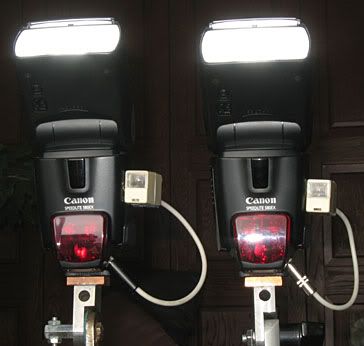
I have the optical trigger held onto the flash with the little Velcro I added to the bottom of the slave. I had an ebay trigger on the camera that I used to trigger a flash and this flash firing caused the slaves in the picture to fire.So the next morning as I was getting ready for work I noticed that I forgot to turn off the one radio receiver that I used to trigger the two slaves. Well at least by having the optical slaves I didn't have any more radios that I forgot to turn off.
I have a question that's not quite related but I'm not sure who else to ask...
ReplyDeleteI would like to trigger slave strobes I bought off ebay that screw into regular light sockets, similar to this:
http://www.shopping.com/Jtl-Jtl-S-45-Ac-Slave-Strobe-Guide-Number-90-Feet-Iso-100/info
My question is, can/will a closely placed white LED be made to trigger these slave flashes? How much light do the sensors in the slaves need to be triggered? Will a high output white LED need to have a short current pulse greater than it can normally handle if illuminated for any extended period of time?
The LEDs I have on hand are the SMT ones mounted on the replacement dome light festoon bulbs that are sold on ebay.
Hi, I like what you have done here. I will give it a go for my Nikon sb24. What was the rating of the photo transistor, if you remember? Ta heath (nz)
ReplyDelete